 CCNCAnimationObjects


Creates a CNC like animation and assigns Geometry Nodes setup for CNC simulation. Can also be used to create crazy objects not possible with CNC. Includes a possibility to easily create animation segments, a camera setup and spark simulation. These additional features can also be used in other projects independent of CNC setup.
CCNC Animation Objects Toolkit for Blender
Table of Contents
- CCNC Animation Objects Toolkit for Blender
- Table of Contents
- Overview
- Key Features
- Usage - Understanding the different Tools
- Creating Animation Segments
- CSV Export & Import
- Camera & Effect Box Tool
- Spark Particle Effects - Visual Enhancement
- Known Issues/Troubleshooting
- Troubleshooting Rendering
- Credits & Acknowledgements
Overview
The CNC Animation Toolkit for Blender is a comprehensive addon designed to create realistic (and impossible) CNC machining animations. It offers different ways of using it, from basic material removal simulation to create objects which are otherwise hard to create to advanced toolpath generation, camera control and visual effects for nicer animations, enabling users to produce compelling visualizations of machining processes.
Ideal for product designers, animators, and enthusiasts who want to simulate CNC operations, generate dynamic sparks, and choreograph complex camera movements for nice animations.
Key Features
- Dynamic CNC Cut Simulation: Apply a Geometry Node setup to your blank object for realistic material removal based on cutter interaction with a blank object.
- Flexible Animation Generation: Utilize pre-defined patterns (Linear, Helix, Circle) for easier cutter and blank movement animation generation.
- Comprehensive Animation Segment Management: Create and manage multiple animation segments with individual settings with also CSV export/import.
- Advanced Camera & Effect Box Control: Independently control camera movements and apply visual effects like fade-ins/outs with a dedicated effect box.
- Interactive Toolpath Preview: Visualize generated toolpaths as lines or with cutter instances.
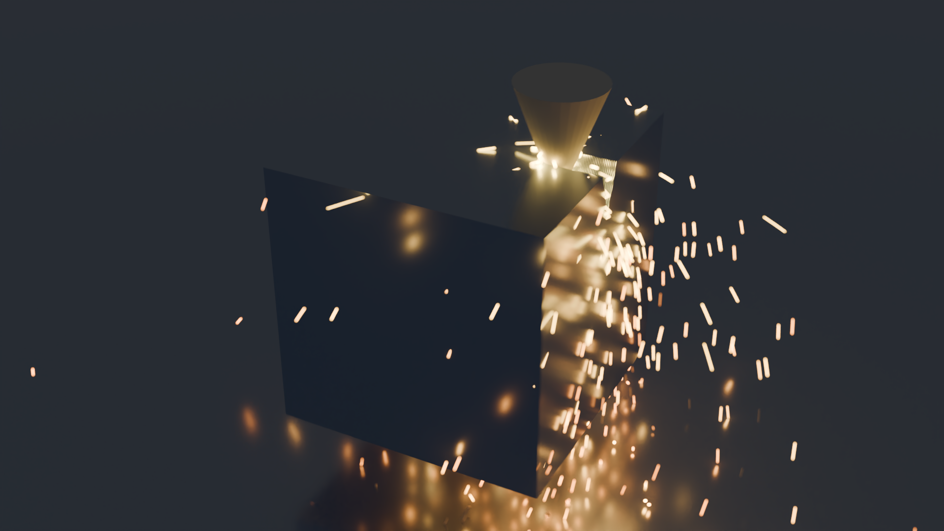
- Realistic Spark Emission: Generate dynamic particle sparks that only appear when the cutter has contact with the material.
Usage - Understanding the different Tools
The CNC Animation Toolkit has different tools onboard, allowing you to use as much or as little of its functionality as needed, from simple simulation enhancement to full scene automation.
Once installed, the addon panel can be found in the 3D Viewport's Sidebar (N-panel) under the 'CCNC Anim' tab.
To use it, you first need to select one object to be the blank and another object to be the cutter.
Core Simulation (Custom Animation)
This can be thought as a fundamental CNC cutting simulation. It generates a Geometry Node setup which can be used to cut the blank object by animating the cutter object through it in any way, the GN simulation setup will automatically apply the material removal effect when you play the animation.
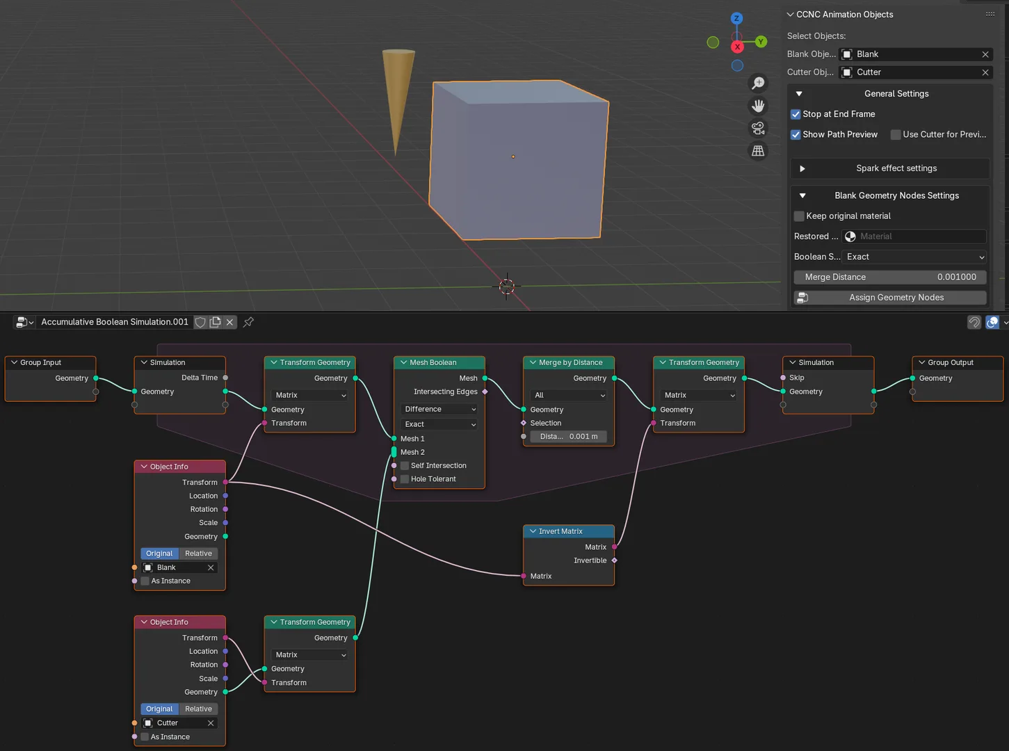
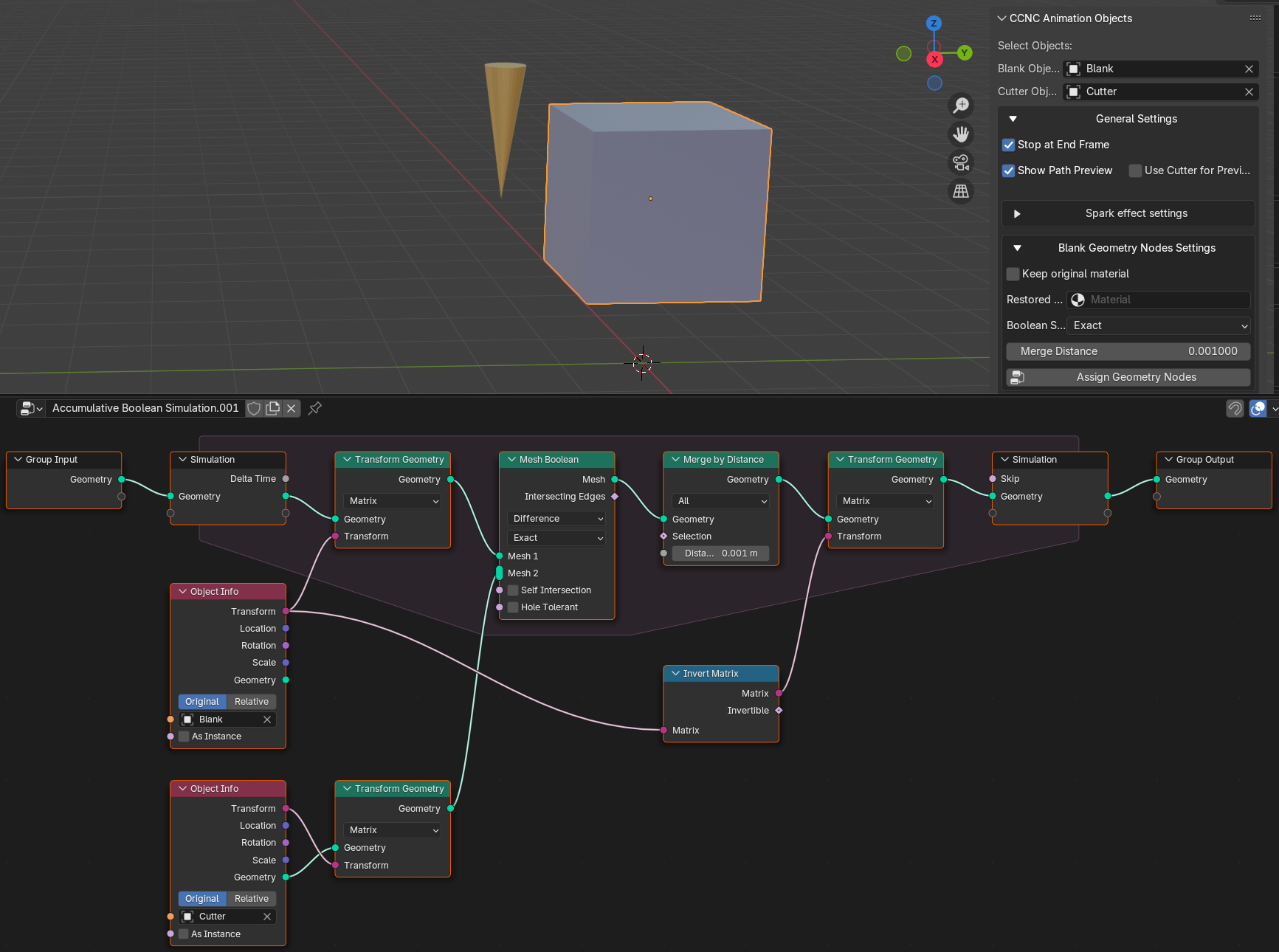
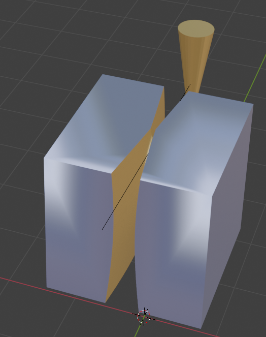
Setting Up Your Scene
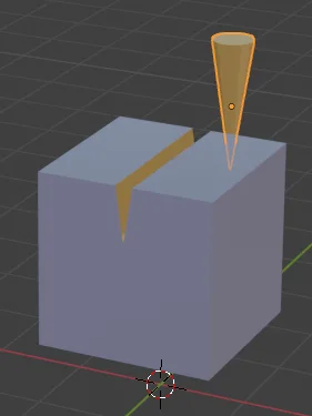
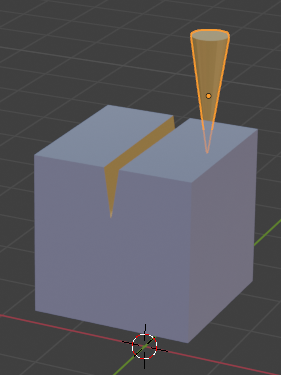
To begin, you need a 'Cutter' object and a 'Blank' object in your scene.
Here we use the standard cube and a cone as example.
The Cutter Object
The 'Cutter' is your animated tool. Its interaction with the 'Blank' drives the cutting simulation. You are free to animate this object using any of Blender's animation tools.
The Blank Object
The 'Blank' is the material being cut. The addon applies a Geometry Node modifier to this object, which visually 'removes' material where the cutter passes through. The Blank Object can be anything you want, not only the cube used here.
Create the Geometry Nodes Setup
Simply open the "General Settings" and there "Blank Geometry Nodes Settings". Here you'll find the button "Assign Geometry Nodes" which will always replace the exististing setup. Please keep in mind that if you change any section in this section here you need to again click this button to create the changed setup. The Blank Object doesn't need to be selected as the object is known through the Blank Object selector at the top.
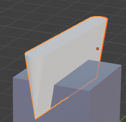
Start the Animation
After the Geometry Nodes setup is done you're ready to use your cutter. You could create any animation which moves the cutter object through the blank object and it will leave a cut in the object when you start the animation. At this point you're already done. Because when the animation ends you can now right click the blank and use "Convert To Mesh" to bake your cut into the Blank object. Now you have a new object and you can go on working with it.
That is indeed the main purpose of this addon: Having an easy way to create complex objects and on the other hand having a tool to test CNC pathes to see the resulting object.
To see the resulting object you should stop the animation at the end. As Blender automatically restarts the animation it is recommended to install the "Unlooped" addon (https://extensions.blender.org/add-ons/unlooped/) which you also can find in the "extensions" list in the Blender preferences. See the documentation there for details.
To make this easier the addon contains several further tools.
Automated Animation Patterns
This provides convenient tools to automatically generate complex cutter and blank animations based on pre-defined patterns, streamlining your workflow. These patterns can be applied to any selected object, not just the designated 'Cutter' and 'Blank' for CNC simulation, "selected" means here you only need to choose these objects as cutter and blank.
(Parameters of all patterns are saved separately so if you decide to test another one you will not lost the other settings. In case of export all parameters of all patterns are always exported.)
The part you can see above is at the lower end of the N-panel of the addon.
All you can see here can be used to create simple or complex animations for these two mesh objects you have chosen as Cutter and Blank. (Of course you can use the standard animation tools of Blender instead, but these tools offer easier methods of creating them for you.)
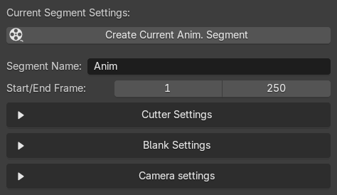
Segment Name and Start/End Frame
The Segment Name is used to create named segments, that follows later, you can ignore this by now. What you need is: A definition of a start and end frame for your animation. The default is 1 to 250.
Cutter Animation Patterns
When you open the Cutter settings you'll find the following settings here:

First, choose from various patterns to define the cutter's movement. These are the current possibilities:
- Linear Path
- Circle
- Helix
- XY Circle Z
- XZ Circle Y
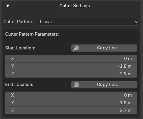
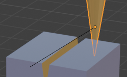
Linear Path:
Animates the cutter in a straight line between a start and end point.
To create the line, use "G" as usual and place your cutter object where it should start, then you can use "Copy Loc." at the "Start Location" setting. Then grab your object again to move it to the end location and click the "Copy Loc." button there - that's all you need. No "I" for keyframing as this will completely be done by the addon later.
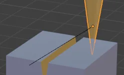
Preview: As you can see the end result only after running the animation there is a simply preview setting: In "General Settings" you'll find these two checkboxes:
 The first one will show you a simple line which is the path you will create (where the cutter follows in the animation), the second one will create one instance of the cutter object for each frame in the start/end frame range to show you what you can expect as cut.
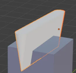
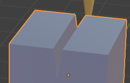
Material Transfer
As you can see in the screenshots above, cutter and blank object hs different materials. This is to show you what happens when you cut the blank object: Blender will transfer the material of the cut surface of the cutter objects which touches the blank object to the surface of the cut. You see that the cut is yellow.
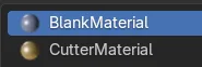
You will not see the added material after animation has run, as the final object is not converted to a mesh. If you do that, you will find both materials in the material list of your blank object:
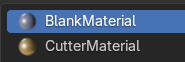
As far as I know there is no possibility to avoid that. Reason may be that your object may already have multiple materials assigned and the Bool operation (which this tool uses for the cut) can then not decide which material to use. So it simply uses the material of the cutter. But that's only my guess.
Fortunately for you there is a switch in the "General Settings" - "Blank Geometry Nodes Settings" in the addon which can adjust this:
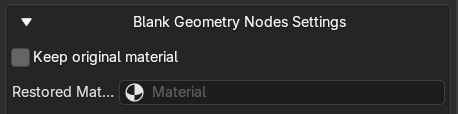
If you use this checkbox and you keep the "Restored Material" setting empty and click "Assign Geometry Nodes" a new node will be added to the GN setup for the blank which restores the material (first found material) of the blank object and sets this to "Restored Material". Instead, you can also select another material here if you maybe want your own material being used for the cut.
With the original material, the cut will now look like this:
 Keep in mind that this may not work if your Blank object already contains more than one material.
The line cut can be used to create CNC movements perfectly. Now let's go on to the other patterns, not all possible settings can of course be used for real CNC machines.
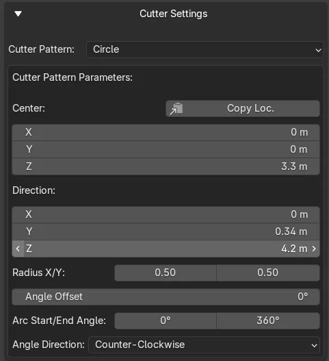
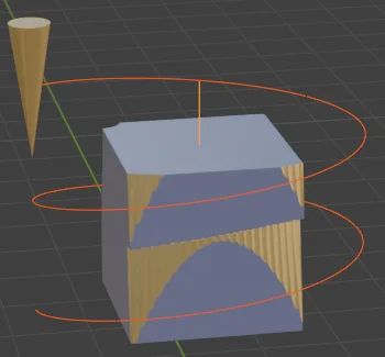
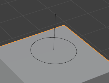
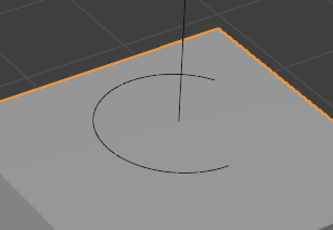
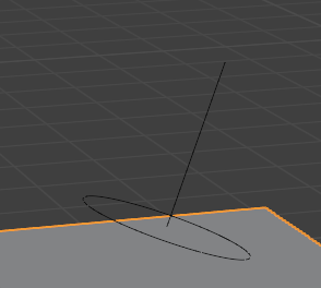
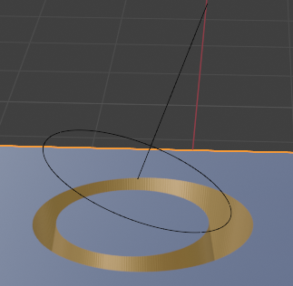
Circle:
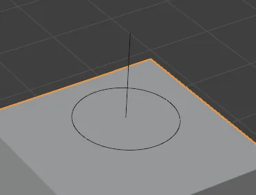
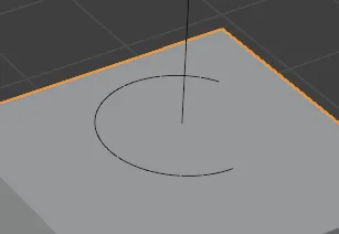
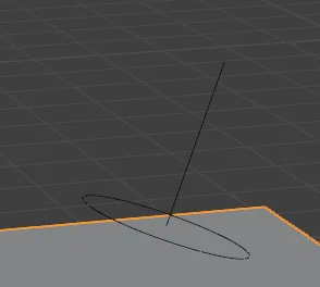
Creates a circle or a segment of a circle. You can also specify a start and end angle, an angle offset and the direction of the cutter animation (clockwise/counter clockwise). Moreover you can create a baseline which always starts in the center of the circle and the end marks the direction of the baseline, which defines the orientation of the plane of the X/Y circle. The direction of this line can be seen as the normal where the circle is the "face". So it doesn't matter how long the line is, it only defines the orientation. Some simple examples:
Available Parameters:
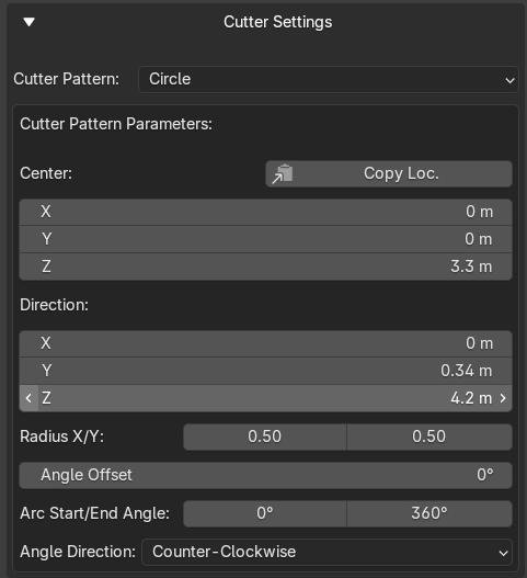
Using the different radius settings for X/Y you can also create ellipses. As above, you can use "Copy Loc." to copy the current cutter object location to the center parameters.
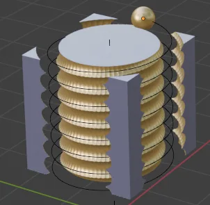
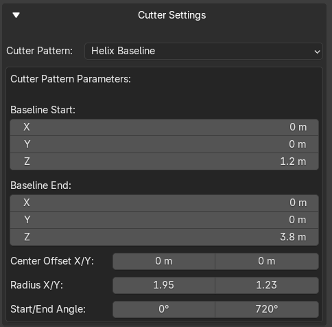
Helix (Baseline):
Creates a helical (spiral) cutting motion. Similar to the circle animation but the baseline definition here splits the circle to a spiral and the length of the baseline defines the orientation of the spiral in space but also the height.
You can set a start and end angle and in opposite to the circle where 360° is maximum (more would not make sense in a circle) you can for example use 6000° to get a greater number of spiral windings in the same height.
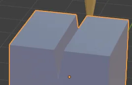
The example above shows a simple helix with the baseline in Z direction and 720° for two windings, it also shows the result of the cut.
Available parameters:
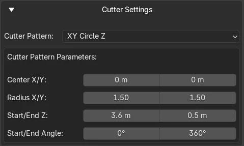
Circle Path (XY, XZ):
These two methods are basically the same as the Helix path. In opposite to that the "XY Circle Z" creates a spiral always in straight Z direction and "XZ Circle Y" creates the spiral path in Y direction. So these are simplifications of the Helix path method and you don't need to define the baseline with coordinates, just the start and end of the spiral in Z or in Y direction and with the center values you can move the spiral in XY or in XZ direction.
The parameters as example for "XY Circle Z":

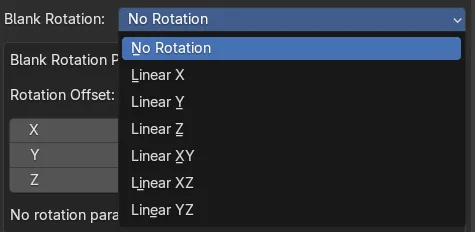
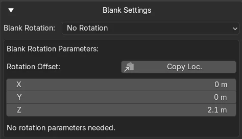
Blank Rotation Patterns
Additionally to the cutter animation you can of course also animate the blank object while the cutter moves through it. This allows for endless possibilities for the resulting cut object.
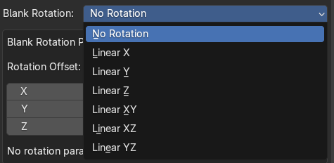
- No Rotation: The blank remains static.
- Linear Rotation (X, Y, Z, XY, XZ, YZ): Rotates the blank object in the animation around one or more axes.
- Standard parameter: The blank initial position

Usually the standard cube is on position 0/0/0. If you want to move the blank object to another position (maybe levitating over a plane or because you want to show it at a rotary module chuck position) you can set that here. Here's also a button to copy the current position of the chosen blank object to these parameters.
In case of "no rotation" a text will be displayed that there are no further parameters to be defined. In all other cases you can change further parameters to describe the rotation.
If any of the rotation options are chosen, two more parameters appear to setup the start and end angle. With these you can specify how often the blank will rotate during start/end frame setting. Means: If you have 250 frames defined and an angle range from 0 to 360° the blank rotates one time during 250 frames. You can set and value you want for both parameters so it will rotate slower or faster, it can also turn in opposite directions with negative values. You can also define to only rotate a half circle - whatever you want.
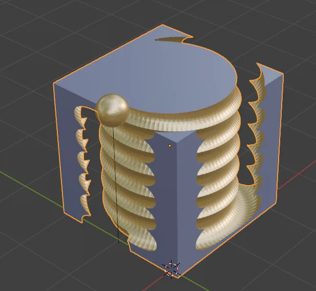
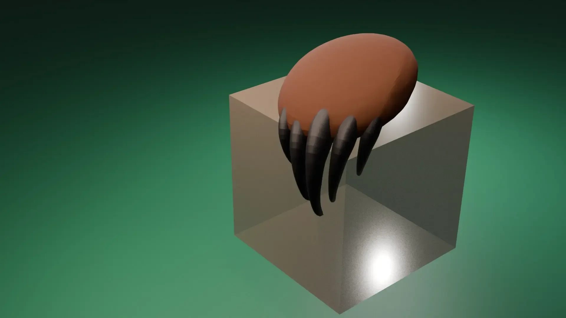
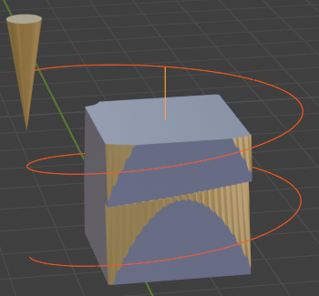
With a spiral movement and simple x rotation you could also get a result like this crazy object:
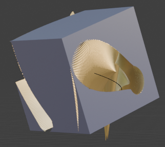
In opposite to the cutter parameters there's only one set of parameters for the blank position and the start/end angle, so choosing another rotation type will not change these.
Other examples
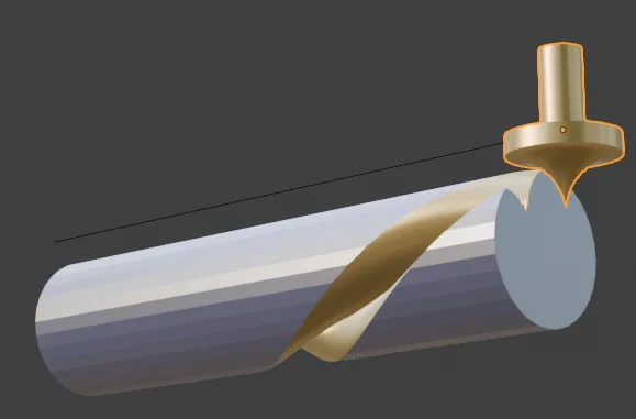
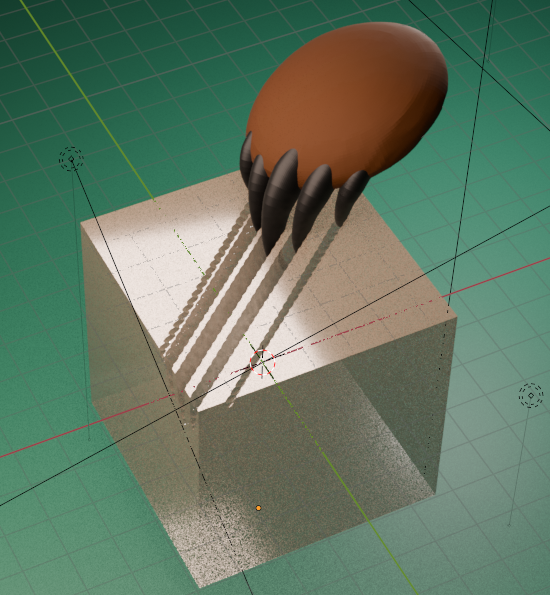
If you change the form of the cutter, the results can be very different, like here with a sphere and a spiral cut:

Of course you can also do it with (here) a linear Z movement of the cutter and a Z rotation of the blank.

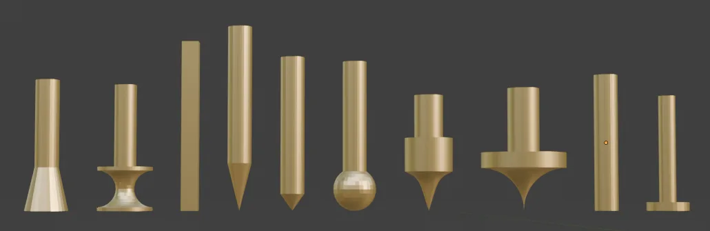
So, just experiment with all kind of forms you like. Maybe with cutters like these?
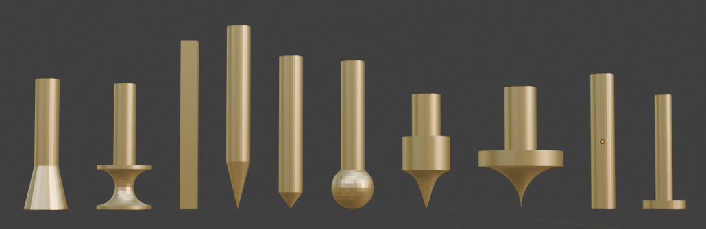
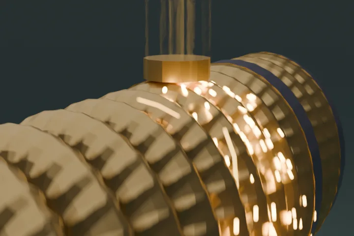
So with that, a simple line animation of the cutter together with a Y rotation of the cylinder blank you can get something like this:

As these have a lot of geometry, use them only for short animations otherwise the Blank object could get too much Geometry which can be a problem for Blender in case of simulation Geometry Nodes like used here. For that reason, also some low-poly cutters are also in the file which are easier to calculate and use.
But of course you can also use the addon not only for CNC simulation. Here's an example of a different "cutter":
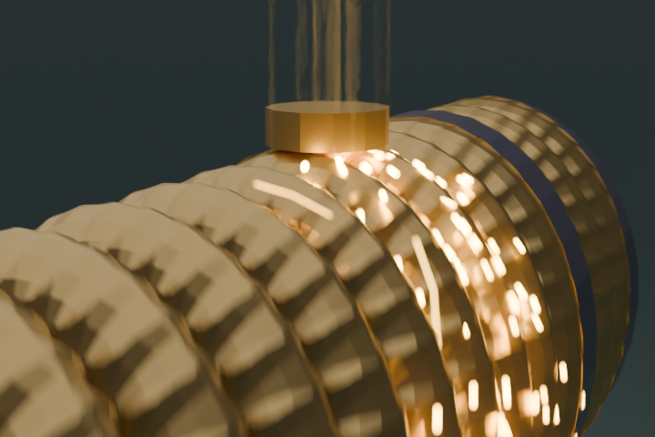
Here is a demo which shows 3 spiral cuts at a Cylinder blank object.
Creating Animation Segments
What if you want to create a more complicate result by combining different cuts? This is where Animation Segments comes in.
Upto here you have used "Create Current Animation Segment" (CCAS Button). Together with the start/end frame setting you could assemble more than one cut. That would be hard to do the more complicate your setup will be. Of course you can still do that and also you can of course just forget about these kind of animation setup and still use all the big animation possibilities Blender itself offers you.
But for quick setup and results without diving into how animations works in Blender this tool allows you to setup a longer animation by using Animation Segments.
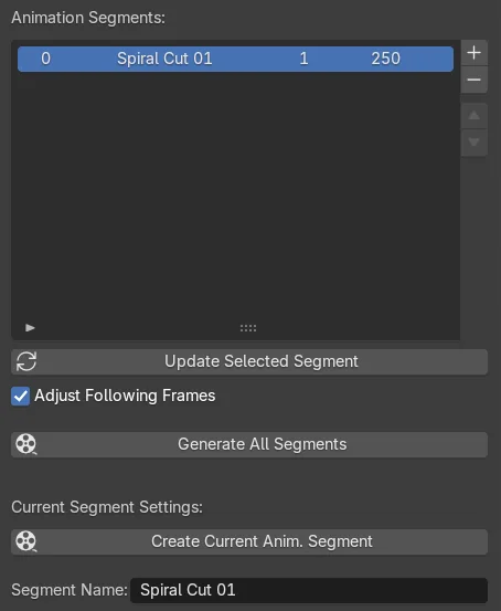
Using the CCAS Button can always be used to quickly create an animation setup which will simply overwrite existing animations of the participated cutter/blank objects in the given start/end frame area. So you can test your animation at all time. If your animation does the cut that you want you can save it into the Animation Segment list which is the blank list in the middle of the addon:

This is where also the "Segment Name" in the current segment settings get a meaning: You can name your segments to appear in the list as you can see in the screenshot. There is also an index number as first column, the start and end frame as third and fourth column and a fifth column which will show a camera icon when the setup contains camera settings (more on camera settings later).
To add or remove a segment, click the "+" or "-" button. The "+" button will take all the current settings as a new entry. If you want to change an existing segment, use the "Update Selected Segment" button instead. Clicking on a row in the list will load the segment settings to the current parameters. You can also use that to copy settings by loading one segment and clicking "+" to create a new segment with the same setting which you then can change and use "Update" to save it back to the list. Keep in mind that you cannot click one line and copy that to an existing one because when you click another row the current settings will be overwritten as the second click loads the settings from there.
But: You can add it as new line, move it with the two arrow buttons where you want it and delete an older one.
As also the frame range is saved you could create frame settings in the same or overlapping ranges. To make that easier you can let the "Adjust Following Frames" enabled. Every time you click "Update" this will automatically recalculate the frame range settings in the following entries. On the other hand, you can also use overlapping animations if you want. So you could create a first segment from 1 to 500 and a second one from 200 to 300 overwriting only this range. The complete animation will always be calculated from top to bottom. Keep in mind that overlapping frame ranges can create unpredictable results if you don't know how to use it.
To create the complete animation, click the "Generate All Segments" button which will overwrite all existing animations for these objects.
CSV Export & Import
To have more possibilities, you can also export the complete list to a CSV (comma separated values) file. This is a standard text file where you have the property names as first row in separated columns and the data in the following rows.
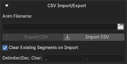
You can find the export and import buttons and all the settings for it in "General Settings" - "CSV Import/Export".
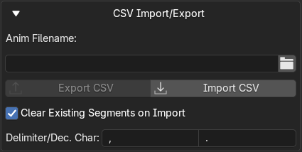
You can set a folder/filename here which will be used to export the current list. If you save it again an already existing file with the same name will not be overwritten, instead an incrementing counter will be added as suffix like "..._0001".
For import there will be always a file dialog where you can choose the desired file.
Additionally there are settings for the column separator and the decimal point character. Both can only be 1 character of your choice. This is useful if you want to edit the CSV file with Excel. In a German Excel you would need ";" as separator and "," as decimal point character, then the columns will be loaded in separated columns in Excel also. In an English Excel you would need "," as separator and "." as decimal point. Make sure that these settings fits to the file you want to import, you cannot save it with one setting and import with another.
You can use the export/import possibility for example to:
- save a list of animation segments and reload it later (for example to use it for a different scene with different blank/cutter objects)
- save a list of segments and import it at the end of the existing one by using the "Clear Existing Segments on Import" checkbox - if you disable it, it will import the data at the end of the current list. This is useful to quickly create bigger animation lists as copy of another. The frame ranges will be adjusted after import.
- save a list of segments to view them as table in Excel edit it there with all the possibilities Excel provides and load it back to the animation segment list after saving the edited file. Make sure that Excel saves it in the expected format as Excel often uses own variations and adds characters where it should not do it. If you are unsure, use another CSV editor instead.
- mix the segments by saving and importing it at the end of the list, then use the up and down button to mix the new segments into the existing list, with also the possibility to automatically adjust all frame settings (simplest way by selecting the first one which loads it into the current settings and directly click the "Update" button)
If that's not enough for you, there is still more to explore in the addon.
Camera & Effect Box Tool
This powerful module provides tools for animating cameras and a special "Effect Box" object. It can be used completely independently of the CNC simulation for any Blender scene, or integrated to create cinematic CNC animations.
The camera and effect box settings are part of the Current Segment Settings so they will also be saved together with the current segment property settings into the Animation Segments if you save it there. It will also be exported and imported with the CSV function.
You find these settings at the bottom of the addon panel in the "Camera Settings" area:
Camera Setup
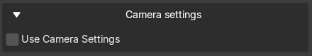
By default the "Use Camera Settings" is switched off. As the effect box (explained later) makes also only sense using a camera this will also open only if you switch this checkbox on.
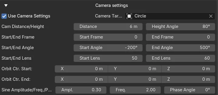
These are the possible settings:
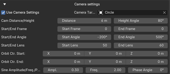
To use the parameters you need to set a target object. This is where the camera will always point to so this is the object you will always see in the camera view, independent of the camera position (except there is an object between the target object and the camera of course). In the screenshot example above the cutter itself is used as target - but that's why you have the option here to choose also something else. That could be the blank object - or an empty object which you maybe want to animate in a different way (animation of such object is not part of the addon, you would need to animate that on your own).
After the setup of the target objects you can now choose with a lot of parameters what the camera should do. (A camera is automatically added with these settings.)
The camera settings are made to automatically create a 360° orbit movement around a hidden orbit object (created as an Empty object automatically). So this orbit point is NOT the target object. The orbit point can be set independently of the target object. For this, you can define the start/end coordinates of the orbit center. That means, if you have defined 1 to 250 as animation segment the camera moves a full circle around the orbit point in 250 frames. At the same time it will automatically rotate itself to always look onto the target object, independently where the orbit object is. The distance and height parameters defines the relative distance between the Orbit point and the height. The distance describes a radius in X/Y plane around the orbit point (NOT the distance to the target object the camera looks on). The height parameter describes the angle between the X/Y plane of the orbit point and the camera focus point.
- So an angle of 0° would mean the camera is on the same Z height as the orbit point (the Empty object) with the defined distance.
- An angle of 90° would mean the camera is directly over the orbit point in Z direction, also with the defined distance.
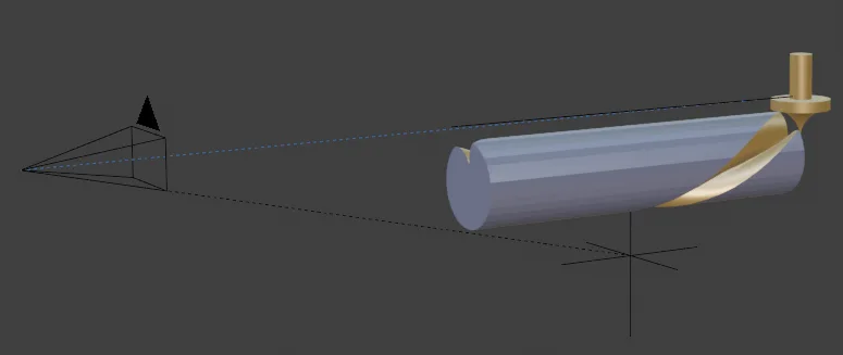
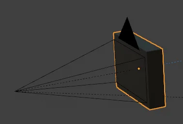
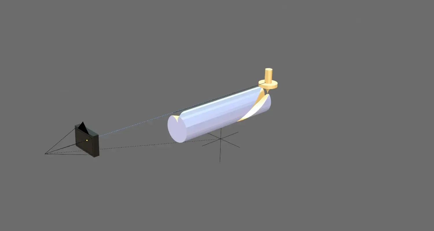
This is how it looks like:
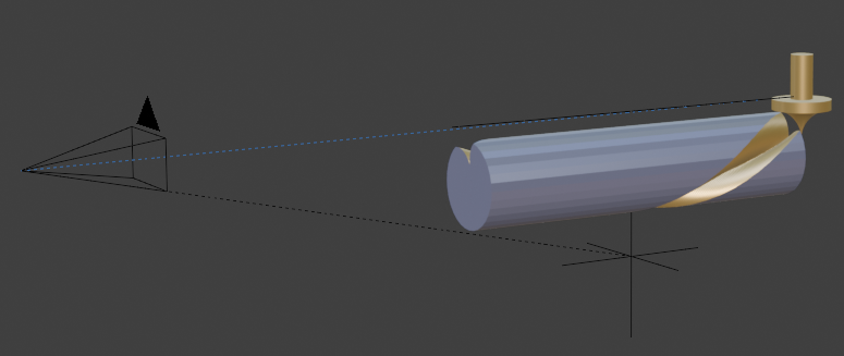
The camera on the left side views to the target object, shown by the blue dotted line, which is the cutter object in this case. The orbit object is the empty XYZ cross at the bottom (invisible in the scene) and the camera will fly around that. This is shown by the black dotted line.
As you can also move the orbit object in a line you can also create elliptical or spiral pathes - and if you set the start and end angle of the camera to the same value, you could also follow a line path without circular movements around the orbit point.
You can also change the lens parameter for a nice zoom effect while animating.
Finally, a start/end frame setting allows you to use a frame range for the camera movement which don't need to be the same as the segment frame range. Setting this (and also the lens parameters) to 0 uses the existing animation segment frame settings. But you could also have a segment frame range from 1 to 250 and a camera frame range from 100 to 200 so the camera will animate only between frames 100 and 200 and not from 1 to 99 and 201 to 250. (Keep in mind that the camera frame range will not be automatically adjusted in the animation segment list, it will always be the same as you set here. If you use 0 for both settings the current animation segment frame range is used.)
At the bottom you can also find three "Sine" values you can change. To not have a too boring camera movement this will add a sine wave movement up and down. You can define the height (amplitude), how often it should move up and down (the frequency) and where to start with the movement (phase angle), at any value in the sine wave you want.
Together with all the other settings explained above you can create crazy camera movements, especially because the target and orbit objects are different and that the target object can be also a third object, visible or not.
To experiment with the camera without the need to always create the complete animation there is a dedicated button "Create Camera Setup" at the bottom which will only setup the camera independent of the other functions of the tool. So you could use this also to create camera movements for any other kind of scenes, not only for the purpose of the addon.
The animation will be created with the standard tools of Blender so once you have created it and you would uninstall the addon your animation would still work in your scene. That is also the case with all the other animations.
Still not enough effects for you? Then maybe the Effect Box explained now is something for you.
The Effect Box
The Effect Box is a special object that can be used to create various visual effects, such as fade-in/out transitions, or acting as a mask.
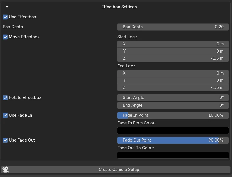
What is meant by "Effect Box"? Here are the settings if you open the Effect Box Settings in the Camera Settings and check all the possible variants:

What is it? It's a cubical box. Nothing else or special. Nevertheless it can do a lot for you.
- it is automatically parented to the camera so it is always rotated and placed together with the camera.
- it is always in a perpendicular position to the camera view axis and is strechted big enough to mask the complete camera view.
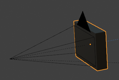
- it has a default material of black with Alpha set to 0 to be completely invisible
This is how it looks like with the default material and Fade In Setting:
First easy usage is, you can use it to fade in or out from/to black (or whatever material color you choose in the settings). For this you have a Fade In and a Fade Out setting where you can set the point in time when the material of the effectbox has reached the Alpha = 0 or Alpha = 1, dependent on Fade In or Fade Out. The default setting is 10% and 90%, means at a value of 10% of the defined frame range the material will be invisible (Fade In ends) and at 90% to last frame the material will get visible completely. Keep in mind that the frame range is dependent on the frame range of the camera setting. If 0 is used there, it is the frame range of the animation segment, otherwise the frame range there.
For more effects you can also use the move and rotate settings. This can be used for example to have a visible material on the effectbox assigned and then move the effectbox for example from top to bottom. If the material is a curtain this would close the scene with a curtain for example.
But whatever you want to do with it is also possible: You could create child objects inside the effectbox and give them physics, for example have some balls rolling in or a fluid or animated objects or whatever. So you have a "scene in the scene" which you can fill to create any kind of special effects without the need to do that later in video editing. For that you can also increase the box depth to get more into it.
Cut, Camera Movement in Sine Waves, Effect Box with Fade In and Fade Out Effect
Still not enough possibilities to create cinematic CNC simulation?
OK, then it's time to add spark particles.
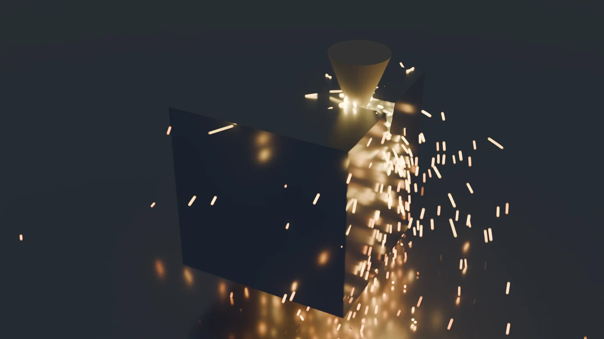
Spark Particle Effects - Visual Enhancement
As part of the core simulation, the addon includes a particle system setup that automatically generates realistic sparks. These sparks are dynamically emitted only when the cutter has physical contact with the Blank Object, enhancing the visual realism of the cutting process.
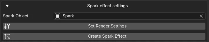
All you need to do is to use the two buttons in the General Settings of the addon:

First one changes the render settings to Cycles as some things in the setup doesn't work with EEVEE. It also sets the calculation mode to GPU and some other settings.
The second button creates the SparkEmitter object as child object of the Cutter Object and creates a Geometry Nodes setup which makes sure the particles are only emitted when the Cutter touches the Blank. (Trick here is that a boolean cut test will be produced and if there is no result = no touch the Geometry of the emitter is moved 1000m down so it's not visible or hidden by a ground object like a plane. The emitter is then forced to continue emitting at this position. Disabling the Geometry does not help as the emitter would then emit from the object origin.)
See below for further information about baking and troubleshooting.
Keep in mind that enabling the Sparks of course costs more calculation time and memory.
A spark object (Icosphere) will be automatically created below the scene, usually hidden by the ground plane. If you want to use a different object you can select it in the Spark Object selector. You can of course also adjust all the settings about the particles like you want. Also a glowing material and collision on the blank object will be created. If you have additional objects in the scene, you need to add collision there on your own (if you want collisions).
Known Issues/Troubleshooting
- Cutter doesn't cut the blank That can happen if the object you use as cutter is not a manifold object. It may nevertheless cut but can also fail at any time. So make sure the cutter object is closed, has no inner geometry and so on. I recommend installing the https://extensions.blender.org/add-ons/print3d-toolbox/?utm_source=blender-4.4.3 "3D Toolbox" extension which is helpful to test that and to repair problems with the object
- Blank disappears while cutter moves into or out of the blank object
- Try to change the number of frames in the animation segment. Moving too fast can result in this problem, depending on the relative position of blank and cutter object. This is a known problem of the Boolean operator in general, not of this addon.
- Artifacts appear during the cut (complete or partial copies of the cutter object added to the blank geometry could also appear several times)
- Can also happen because of the number of frames for a cut.
- Can happen if the geometry of the blank gets too complicate (maybe after several crossing cuts).
- For that purpose you find "Boolean Solver" and "Merge Distance" in the General Settings -> Blank Geometry Nodes Settings. These are copies of the corresponding values from the nodes, for convenience exposed here, but you can also change that directly in the node setup of the Blank object if you want.
- Sometimes "Exact" is better that "Float", sometimes a change in the Merge Distance can solve the problem - there is no rule which solves all. Also a general problem of the Boolean Mesh operator, not of the addon.
- Camera distance/height not as expected The camera is set as child object to the orbit controller object (the empty object with X/Y/Y lines). If there is an issue with the scaling/rotation you need to apply transform (rotation/scale, not location) to the Empty object and recalculate the camera setup. After that the distance/height should be as expected.
- Crash when calculating animation There can be several reasons why this happens, i.e. memory gets low. The addon in general is not the reason as it only sets the values and parameters of everything included in Blender. So if Blender crashes it is maybe because you set too small movements while cutting which can exponentially increase mesh data of the blank object and this together with a simulation Geometry Node setting can cause memory problems.
Troubleshooting Rendering
If you want to render your animation you should pre-calculate certain things using Blender's bake tools.
- The renderer doesn't always produce the same result as you see in preview in the 3D scene. I have no idea why, maybe the GN setup is not calculated fast enough or accurate enough.
- In case of particle effects (sparks here) the particle calculation is often not as expected. That all has nothing to do with the addon, you need to adjust the settings of particles if needed.
- Bake Tools:
- To get better animation rendering results, try to bake both kind of simulations in this setup.
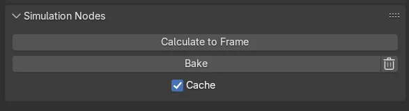
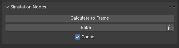
- First one is on the blank object which gets the cut. As this uses a simulation GN setup, go to the "Physics" tab on the right side after selecting the blank object and use the "Cache" checkbox and click "Bake". This will bake the whole animation between start and end frame so it is not simulated anymore. You can see the difference if you move the current frame in the animation window: In simulation mode you get different cuts in relation how fast you move it, in baked mode you see the correct and complete cut at any time.
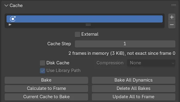
- Second one (if you have enabled Spark effect) is in the particle tab after you have selected the Spark Emitter Object (child object of the cutter object).
 Here you can use "Bake All Dynamics" which also goes through all frames from start to end frame and save the particles in a cache so they do not get calculated at each animation playing.
Look especially to "x frames in memory", if everything is right after calculation it should be the same as the number of frames in your animation.
Here you can use "Bake All Dynamics" which also goes through all frames from start to end frame and save the particles in a cache so they do not get calculated at each animation playing.
Look especially to "x frames in memory", if everything is right after calculation it should be the same as the number of frames in your animation.- Blank Object disappears during animation: For whatever reason I couldn't find out the blank object can disappear during rendering of the animation as if the baked data would have been deleted in the meantime. This seems to be a bake problem, not the Bool operation problem mentioned above. Maybe it helps saving the cache to disk but I didn't tried that. In general, following may help:
- Use a single file export: Instead of using an export format like MP4 use a single picture format like PNG as export. If you create a folder for that, each frame will be rendered as one PNG file which you can easily glue together later in a video software of your choice (also possible with Blender's video editor, I think). The advantage: If you stop the animation because maybe your blank object is not on the output anymore you can resume it simply by unchecking the "Overwrite" checkbox in the output settings. Blender will then resume at the frame where you stopped rendering. Of course you need to delete all frame PNGs from the defect one to the end in Explorer (if you use Windows).
- In general, if you don't need a 4K video and a cinematic output, use smaller output formats - this calculates a lot faster and you have less memory problems.
Credits & Acknowledgements
Special thanks to ChatGPT, Gemini, Claude and Copilot for faster code creation and code revision and some good feature ideas.
What's New
1.2.1 June 29th, 2025
Little bugfix (error when clicking "Create Spark Effect")